

Block Diagram Of The Closed-loop Feedback Control System For HTS ...
Block Diagram Of The Closed-loop Feedback Control System For HTS ... Manufacturers today face many hurdles in their manufacturing applications Process parameters can range from one application to the next While some applications require very little precision and Figure 1 shows a block diagram of the dynamometer’s architecture Table 1 describes each of the dynamometer components with the reasons for selection 1 Shown is a block diagram of dynamometer The

Block Diagram Of The Closed-loop Feedback Control System For HTS ...
Block Diagram Of The Closed-loop Feedback Control System For HTS ...

SOLVED: A Closed-loop Block Diagram Of A Feedback Control System Is ...
SOLVED: A Closed-loop Block Diagram Of A Feedback Control System Is ...
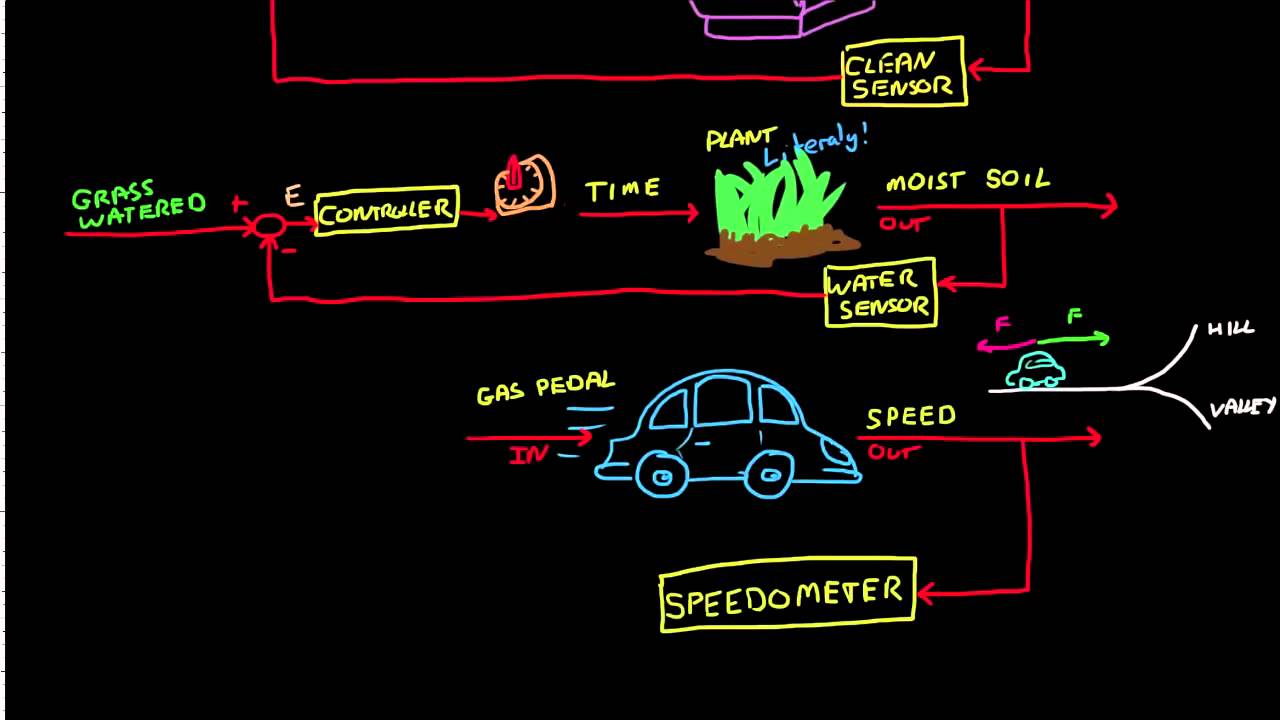
Control Systems Lectures - Closed Loop Control
Control Systems Lectures - Closed Loop Control
Related image with block diagram of the closed loop feedback control system for hts


![Closed Loop Feedback Control Block Diagram [23] | Download Scientific ...](https://i0.wp.com/www.researchgate.net/publication/370980704/figure/fig5/AS:11431281160878811@1684895141228/Closed-Loop-Feedback-Control-Block-Diagram-23_Q320.jpg?resize=91,91 "Closed Loop Feedback Control Block Diagram [23] | Download Scientific ...")

 Control System And | Chegg.com")
 Loop Control System ...")


Related image with block diagram of the closed loop feedback control system for hts


About "Block Diagram Of The Closed Loop Feedback Control System For Hts"
Comments are closed.