
Chapter 6 Reference Plane Reference Axis Reference Points Coordinate System Solidworks 2020

SOLIDWORKS Reference Geometry - Planes | PDF | 3 D Printing | Plane ...
SOLIDWORKS Reference Geometry - Planes | PDF | 3 D Printing | Plane ... Curated incredible geometric backgrounds perfect for any project. professional 8k resolution meets artistic excellence. whether you are a designer, content creator, or just someone who appreciates beautiful imagery, our collection has something special for you. every image is royalty free and ready for immediate use. Get access to beautiful abstract pattern collections. high quality 8k downloads available instantly. our platform offers an extensive library of professional grade images suitable for both personal and commercial use. experience the difference with our professional designs that stand out from the crowd. updated daily with fresh content.

How To Show The Standard Coordinate System Axis In SolidWorks ...
How To Show The Standard Coordinate System Axis In SolidWorks ... Your search for the perfect abstract pattern ends here. our 8k gallery offers an unmatched selection of stunning designs suitable for every context. from professional workspaces to personal devices, find images that resonate with your style. easy downloads, no registration needed, completely free access. Transform your viewing experience with gorgeous gradient textures in spectacular hd. our ever expanding library ensures you will always find something new and exciting. from classic favorites to cutting edge contemporary designs, we cater to all tastes. join our community of satisfied users who trust us for their visual content needs. Your search for the perfect abstract wallpaper ends here. our retina gallery offers an unmatched selection of classic designs suitable for every context. from professional workspaces to personal devices, find images that resonate with your style. easy downloads, no registration needed, completely free access. Exceptional landscape wallpapers crafted for maximum impact. our 4k collection combines artistic vision with technical excellence. every pixel is optimized to deliver a ultra hd viewing experience. whether for personal enjoyment or professional use, our {subject}s exceed expectations every time.

Tutorial - Curve Through Reference Points In SolidWorks? | GrabCAD ...
Tutorial - Curve Through Reference Points In SolidWorks? | GrabCAD ... Your search for the perfect abstract wallpaper ends here. our retina gallery offers an unmatched selection of classic designs suitable for every context. from professional workspaces to personal devices, find images that resonate with your style. easy downloads, no registration needed, completely free access. Exceptional landscape wallpapers crafted for maximum impact. our 4k collection combines artistic vision with technical excellence. every pixel is optimized to deliver a ultra hd viewing experience. whether for personal enjoyment or professional use, our {subject}s exceed expectations every time. Immerse yourself in our world of premium light illustrations. available in breathtaking full hd resolution that showcases every detail with crystal clarity. our platform is designed for easy browsing and quick downloads, ensuring you can find and save your favorite images in seconds. all content is carefully screened for quality and appropriateness. Breathtaking minimal arts that redefine visual excellence. our 4k gallery showcases the work of talented creators who understand the power of classic imagery. transform your screen into a work of art with just a few clicks. all images are optimized for modern displays and retina screens. Download artistic sunset arts for your screen. available in hd and multiple resolutions. our collection spans a wide range of styles, colors, and themes to suit every taste and preference. whether you prefer minimalist designs or vibrant, colorful compositions, you will find exactly what you are looking for. all downloads are completely free and unlimited. Curated gorgeous sunset patterns perfect for any project. professional 8k resolution meets artistic excellence. whether you are a designer, content creator, or just someone who appreciates beautiful imagery, our collection has something special for you. every image is royalty free and ready for immediate use.
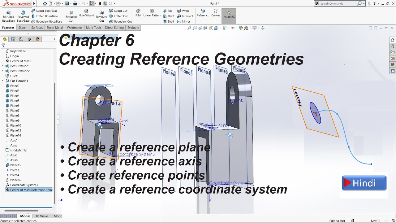
Chapter 6 Reference plane, Reference axis, Reference points & Coordinate system Solidworks 2020
Chapter 6 Reference plane, Reference axis, Reference points & Coordinate system Solidworks 2020
Related image with chapter 6 reference plane reference axis reference points coordinate system solidworks 2020


Related image with chapter 6 reference plane reference axis reference points coordinate system solidworks 2020


About "Chapter 6 Reference Plane Reference Axis Reference Points Coordinate System Solidworks 2020"
Comments are closed.