
 Diagram Determined For The ...")
Continuous-cooling-transformation (CCT) Diagram Determined For The ...
Continuous-cooling-transformation (CCT) Diagram Determined For The ... Equation 5 or 7 can be used for the conversion of cct diagram to ttt diagram depending on constant cooling rate or case of cooling rate that can be expressed in analytical or empirical form. Abstract continuous cooling transformation (cct) diagrams are widely used when heat treating steels and represent which type of phase will occur in a material as it is cooled at different cooling rates.
 Diagram Determined For The ...")
Continuous-cooling-transformation (CCT) Diagram Determined For The ...
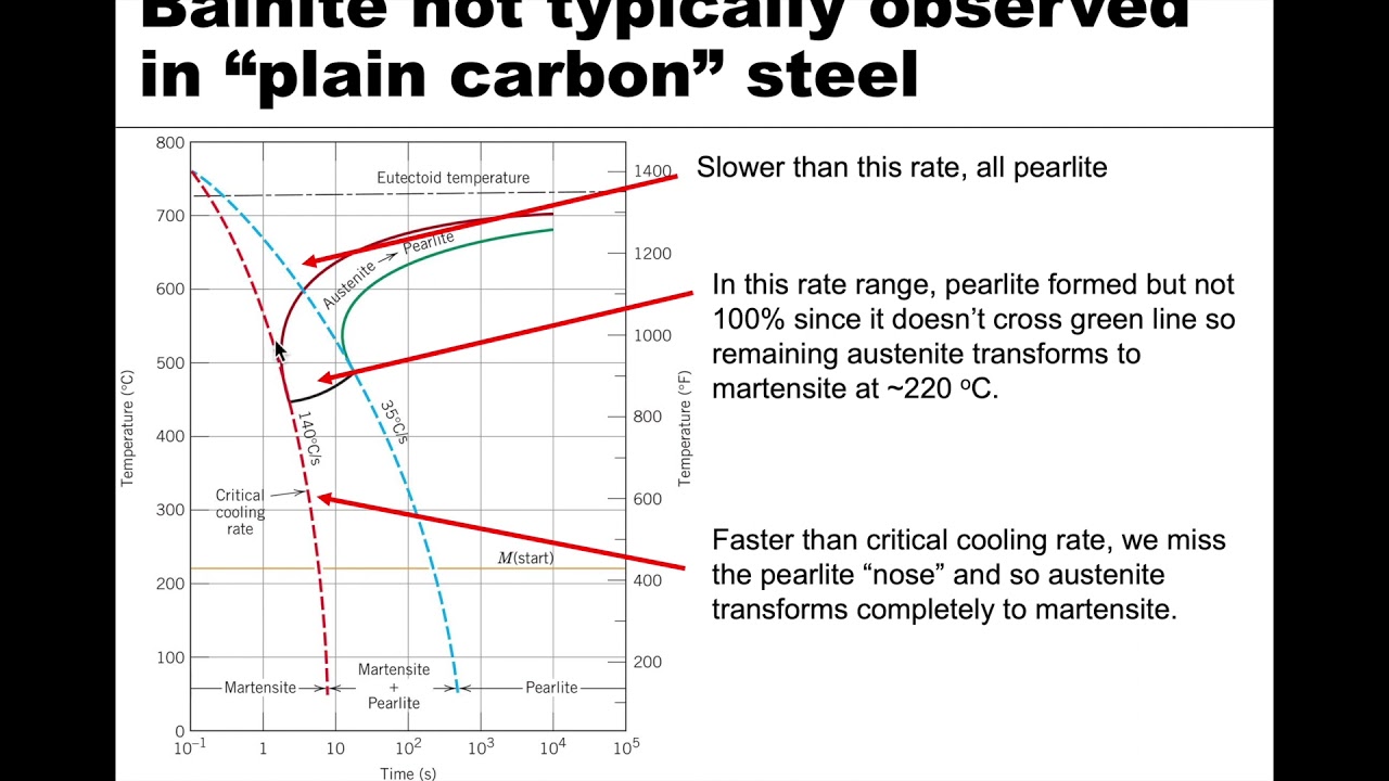
Continuous-cooling-transformation (CCT) Diagram Determined For The ... Multiple cooling curves generate data points that comprise the cct diagram when plotted together. this diagram predicts phase transformations for similar cooling conditions. The continuous cooling diagram (cct diagram) gives a more accurate picture for heat treatments involving continuous cooling. the cct diagram is a plot of temperature versus the logarithm of time for a steel alloy of definite composition. The objective of this paper is to determine the cct diagram of a si–cu alloyed ductile iron for high strength and high plasticity crankshafts, and to support the optimization of the heat treatment process. Continuous cooling transformation (cct) diagrams are usually plotted using dilatometer tests on a hot simulator and metallographic analysis. however, for some steel grades it is not sufficient to use conventional methods to plot cct diagrams.
 Diagram Determined For The ...")
Continuous-cooling-transformation (CCT) Diagram Determined For The ...
Continuous-cooling-transformation (CCT) Diagram Determined For The ... The objective of this paper is to determine the cct diagram of a si–cu alloyed ductile iron for high strength and high plasticity crankshafts, and to support the optimization of the heat treatment process. Continuous cooling transformation (cct) diagrams are usually plotted using dilatometer tests on a hot simulator and metallographic analysis. however, for some steel grades it is not sufficient to use conventional methods to plot cct diagrams. This type of cct diagram is a convenient means of determining the microstructure in the center of a round bar that has been austenitized and then air, oil, or water quenched. Cct diagrams allow predictions of hardness and microstructure in simple shapes quenched in oil, water, or other quenchants. in the last column, we discussed the construction and application of time temperature transformation or isothermal transformation diagrams. Purpose: the paper presents empirical formulas for the calculation of continuous cooling transformation (cct) diagram basing on the chemical composition and austenitizing temperature. Abstract: continuous cooling transformation (cct) diagrams are widely used when heat treating steels and represent which type of phase will occur in a material as it is cooled at different cooling rates.
 Diagram For CP-IH ...")
Experimental Continuous Cooling Transformation (CCT) Diagram For CP-IH ...
Experimental Continuous Cooling Transformation (CCT) Diagram For CP-IH ... This type of cct diagram is a convenient means of determining the microstructure in the center of a round bar that has been austenitized and then air, oil, or water quenched. Cct diagrams allow predictions of hardness and microstructure in simple shapes quenched in oil, water, or other quenchants. in the last column, we discussed the construction and application of time temperature transformation or isothermal transformation diagrams. Purpose: the paper presents empirical formulas for the calculation of continuous cooling transformation (cct) diagram basing on the chemical composition and austenitizing temperature. Abstract: continuous cooling transformation (cct) diagrams are widely used when heat treating steels and represent which type of phase will occur in a material as it is cooled at different cooling rates.
 Diagram For Alloy AA6061 ...")
Continuous Cooling Transformation (CCT) Diagram For Alloy AA6061 ...
Continuous Cooling Transformation (CCT) Diagram For Alloy AA6061 ... Purpose: the paper presents empirical formulas for the calculation of continuous cooling transformation (cct) diagram basing on the chemical composition and austenitizing temperature. Abstract: continuous cooling transformation (cct) diagrams are widely used when heat treating steels and represent which type of phase will occur in a material as it is cooled at different cooling rates.
MSE 201 S21 Lecture 38 - Module 3 - Continuous-Cooling Diagrams
MSE 201 S21 Lecture 38 - Module 3 - Continuous-Cooling Diagrams
Related image with continuous cooling transformation cct diagram determined for the
 Diagram Determined For The ...")
 Diagram Determined For The ...")
 Diagram Determined For The ...")
 Diagram For CP-IH ...")
 Diagram For Alloy AA6061 ...")

 Diagram Revealing That ...")
 Determined For The ULCB ...")
: (a ...")
 Diagram For Low-carbon F82H ...")
 Diagram For Steel Used ...")
 Diagram For Steel Used ...")
Related image with continuous cooling transformation cct diagram determined for the

 Diagram Lecture 3 Part 1 Heat Treatment")

 Diagram? - Civil Engineering Explained")
About "Continuous Cooling Transformation Cct Diagram Determined For The"
Comments are closed.