Rlc Parallel Circuit Impedance Phasor Diagram Electri Vrogue Co

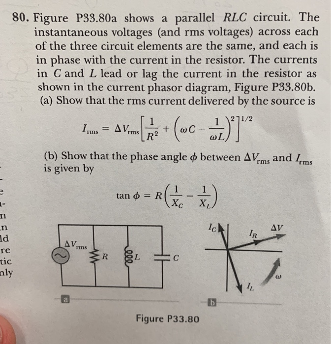
Impedance Phasor Diagram Rlc Circuit Circuit Diagram Regarding the rlc parallel circuit, this article will explain the information below. an rlc parallel circuit is an electrical circuit consisting of a resistor \ (r\), an inductor \ (l\), and a capacitor \ (c\) connected in parallel, driven by a voltage source or current source. The phasor diagram for a parallel rlc circuit is produced by combining together the three individual phasors for each component and adding the currents vectorially.

Phasor Diagram Rlc Circuit Parallel As a homeowner, business owner, or electrician, understanding parallel rlc circuit phasor diagrams is an essential part of making sure your electrical systems are running properly. in this blog post, we’ll discuss what exactly a parallel rlc circuit phasor diagram is and why it’s important. This guide covers parallel rl circuit analysis, phasor diagram, impedance & power triangle, and several solved examples along with the review questions answers. Understand the phasor diagram of a parallel rlc circuit and how it helps analyze the voltage and current behavior in the circuit. Learn how to analyze and interpret phasor diagrams in parallel rlc circuits, focusing on impedance, voltage, and current relationships in ac systems.

Phasor Diagram Rlc Parallel Circuit Circuit Diagram Understand the phasor diagram of a parallel rlc circuit and how it helps analyze the voltage and current behavior in the circuit. Learn how to analyze and interpret phasor diagrams in parallel rlc circuits, focusing on impedance, voltage, and current relationships in ac systems. In this article, we will study a parallel rlc circuit and analyze it to obtain different parameters such as current, voltage, impedance, admittance, etc. The concept of a parallel rlc circuits can be a little more mathematically difficult than for series rlc circuits. in parallel circuit, the voltage across each element remains the same and the current gets divided in each component depending upon the impedance of each component. Compute complex impedance and system voltage in parallel rlc circuits. determine the equivalent value of multiple ac current sources in parallel. draw phasor diagrams for impedance susceptance and component currents in parallel rlc circuits. The phasor diagram for rlc circuit in parallel is an invaluable tool for engineers and electricians. when properly understood, it can allow them to efficiently analyze circuits and make the necessary adjustments to ensure a smooth and reliable performance.

Parallel Rlc Circuit Phasor Diagram Circuit Diagram In this article, we will study a parallel rlc circuit and analyze it to obtain different parameters such as current, voltage, impedance, admittance, etc. The concept of a parallel rlc circuits can be a little more mathematically difficult than for series rlc circuits. in parallel circuit, the voltage across each element remains the same and the current gets divided in each component depending upon the impedance of each component. Compute complex impedance and system voltage in parallel rlc circuits. determine the equivalent value of multiple ac current sources in parallel. draw phasor diagrams for impedance susceptance and component currents in parallel rlc circuits. The phasor diagram for rlc circuit in parallel is an invaluable tool for engineers and electricians. when properly understood, it can allow them to efficiently analyze circuits and make the necessary adjustments to ensure a smooth and reliable performance.

Comments are closed.