Solved A For The Circuit Shown In The Figure Figure 1 Find Chegg

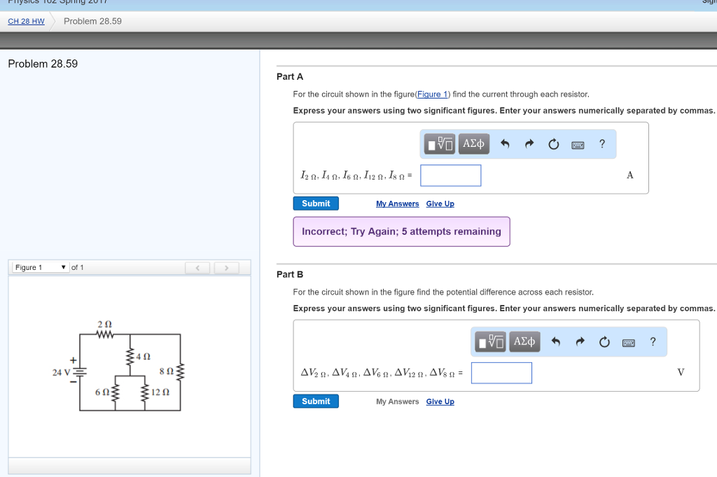
Solved For The Circuit Shown In The Figure Figure 1 Find Chegg Question: for the circuit shown in the figure (figure 1), find the current through and the potential difference across each resistor. for the steps and strategies involved in solving a similar problem, you may view a video tutor solution. Question: part a consider the situation shown in the figure below (figure 1). a 1000 v rms source delivers power to a load. the load consumes 150 kw with a power factor of 28 percent lagging. find the phasor i, assuming that the capacitor is not connected to the circuit enter your answer using polar notation. express argument in degrees.

Solved Consider The Circuit Shown In Figure 1 Figure 1 Of Chegg Suppose that r1 = 16 r. determine the closed loop voltage gain of the circuit shown in (figure 1), assuming an ideal op amp. express your answer to three significant figures. a aeq vec au = submit previous answers request answer x incorrect; try again; 2 attempts remaining figure < 1 of 1 r provide feedback w r 2 r r. The small circuit is not connected in any way to the large one. the wire of the small circuit has a resistance of 1. 2 Ω m Ω m and contains 2 4 loops. the large circuit is a rectangle 2. 0 mm by 4. 0 mm, while the small one has dimensions aa = 1 1. 0 cmcm and bb = 2 0. 0 cmcm . the distance cc is 4. 0 cmcm . (the. There are 4 steps to solve this one. part a for the circuit shown in the figure (figure 1) find the current through each resistor express your answers using two significant figures. enter your answers numerically separated by commas. Question: review i cin the circuit shown in (figure 1), e=12.0v,r=18.0Ω, and l=37.5mh. switch s1 has been closed for a long time and switch s2 is open. at t=0 you open switch s1 and close switch s2. at t=0.700ms, find the current.express your answer with the appropriate units. part gat t=0.700ms find the rate of.

Solved For The Circuit Shown In The Figure Figure 1 Find Chegg There are 4 steps to solve this one. part a for the circuit shown in the figure (figure 1) find the current through each resistor express your answers using two significant figures. enter your answers numerically separated by commas. Question: review i cin the circuit shown in (figure 1), e=12.0v,r=18.0Ω, and l=37.5mh. switch s1 has been closed for a long time and switch s2 is open. at t=0 you open switch s1 and close switch s2. at t=0.700ms, find the current.express your answer with the appropriate units. part gat t=0.700ms find the rate of. Question: a) for the circuit shown in the figure, determine the current in the 7.0 ohms resistor. b) for the circuit shown in the figure, determine the current in the 8.0 ohms resistor. c) for the circuit shown in the figure, determine the current in the 4.0 ohms resistor. please show detailed work. thank you. 3) for the circuit shown in the figure, what is the current through resistor r1? e1 6.0 v e2 3.0 v r1 | 100 Ω r2 200 r3 | 300 Ω | r2 r1 r3 82 e1. Question: in the circuit shown in the (figure 1), the switch has been in position a for a long time. at t=0, it moves instantaneously from a to b. write the expression for vo(t) for t≥0. assume t is in seconds. (solved): problem 1 for the circuit shown in figure 1, assume an ideal op amp and find: v^( ) i (1) i (2) v (0 problem 1 for the circuit shown in figure 1, assume an ideal op amp and find: v^( ) i (1) i (2) v (0) (v (0)) (v (i)) i (l) figure 1 i (0).

Solved Review Consider The Circuit Shown In Figure Figure Chegg Question: a) for the circuit shown in the figure, determine the current in the 7.0 ohms resistor. b) for the circuit shown in the figure, determine the current in the 8.0 ohms resistor. c) for the circuit shown in the figure, determine the current in the 4.0 ohms resistor. please show detailed work. thank you. 3) for the circuit shown in the figure, what is the current through resistor r1? e1 6.0 v e2 3.0 v r1 | 100 Ω r2 200 r3 | 300 Ω | r2 r1 r3 82 e1. Question: in the circuit shown in the (figure 1), the switch has been in position a for a long time. at t=0, it moves instantaneously from a to b. write the expression for vo(t) for t≥0. assume t is in seconds. (solved): problem 1 for the circuit shown in figure 1, assume an ideal op amp and find: v^( ) i (1) i (2) v (0 problem 1 for the circuit shown in figure 1, assume an ideal op amp and find: v^( ) i (1) i (2) v (0) (v (0)) (v (i)) i (l) figure 1 i (0).

Comments are closed.