Solved In The Circuit Shown In Figure 1 The Potential Chegg

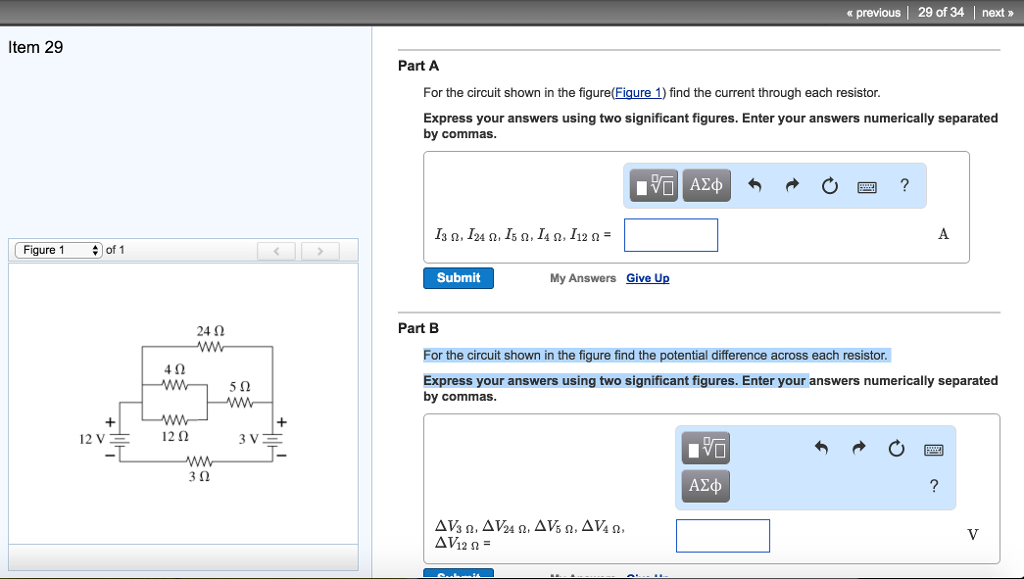
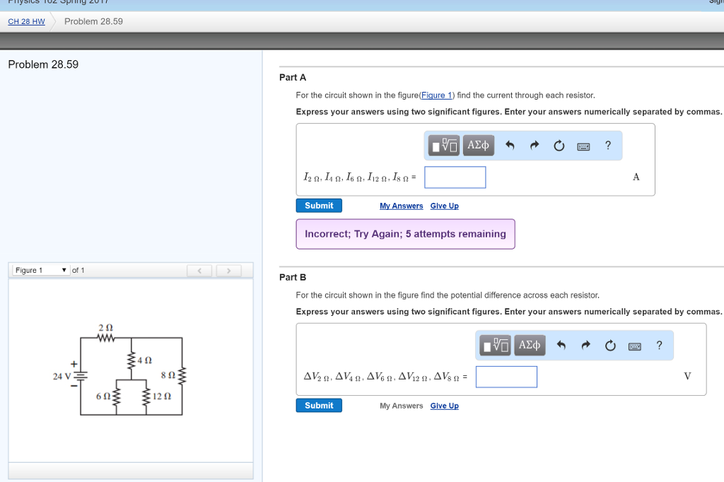
Solved For The Circuit Shown In The Figure Figure 1 Find Chegg Question: in the circuit shown in (figure 1), the potential difference across ab is 26.0 v .figure1 of 1part bcalculate the charge on the 5.00μf capacitor.express your answer in microcoulombs to three significant figures.q2=μcprevious answersrequest answerincorrect; try againpart ccalculate the charge on the 6.00μf capacitor.express your answer in microcoulombs. In the circuit shown in (figure 1), the potential difference across ab is 21.5 v. your solution’s ready to go! enhanced with ai, our expert help has broken down your problem into an easy to learn solution you can count on.

Solved A For The Circuit Shown In The Figure Figure 1 Find Chegg The switch in the circuit in (figure 1) has been closed for a long time and opens at t=0.v=140v.figure1 of 1calculate the initial energy stored in the inductor.express your answer to three significant figures and include the appropriate units.w(0)= request answercalculate the initial value of i.express your answer to three significant. Question: problem 10. consider the circuit shown in the figure below. switch s is closed at t=0,causing a current i1 through the "inductive branch" and a current i2 through the "capacitivebranch." the initial charge on the capacitor is zero, and the charge at t is q2. Question: in the circuit shown in (figure 1), the potential difference across ab is 25.5 v. figure 3.00 f 5.00 f 6.00 μf 1 of 1 > part a calculate the charge on the 3.00 uf capacitor. express your answer with the appropriate units. Solved 2. using the rules of capacitor combination, it is. solved part 1: capacitor. . build the circuit in below using. solved use capacitor combination circuit as shown in the. chegg switched capacitor circuits: basic building blocks and. solved the capacitor in the circuit shown below is initially. solved for each of the following.

Solved For The Circuit Shown In The Figure Figure 1 Find Chegg Question: in the circuit shown in (figure 1), the potential difference across ab is 25.5 v. figure 3.00 f 5.00 f 6.00 μf 1 of 1 > part a calculate the charge on the 3.00 uf capacitor. express your answer with the appropriate units. Solved 2. using the rules of capacitor combination, it is. solved part 1: capacitor. . build the circuit in below using. solved use capacitor combination circuit as shown in the. chegg switched capacitor circuits: basic building blocks and. solved the capacitor in the circuit shown below is initially. solved for each of the following. Electric circuits. nodal and mesh analysis editdiazdesantos theory and solved problems. example 1.0.1. in the circuit represented in fig. 1.1, obtain the required equations for the calculation of the voltages and currents of every element. the nodes and closed circuit paths have been remarked, where the corresponding kirchhof’s laws will be. In the circuit shown in the figure below, the current supplied by the battery is: 1. \(2~\text a\) 2. \(1~\text a\) 3. \(0.5~\text a\) 4. \(0.4~\text a\) current electricity current electricity physics practice questions, mcqs, past year questions (pyqs), ncert questions, question bank, class 11 and class 12 questions, ncert exemplar questions and pdf questions with answers, solutions. The variation of the instantaneous current \((i)\) and the instantaneous emf \((e)\) in a circuit are shown in the figure. which of the following statements is correct? 1.the voltage lags behind the current by \(\frac{\pi}{2}\).2.the voltage leads the current by \(\frac{\pi}{2}\).3.the voltage and the current are in phase.4. the voltage leads the current by \(\pi\). F. calculate the potential difference across the 6.00 μfμf capacitor. there are 2 steps to solve this one. not the question you’re looking for? post any question and get expert help quickly.

Comments are closed.