Solved Q2 The Pump Shown In Figure Below Adds 25 Kw To The Chegg

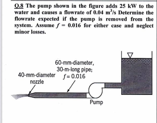
Solved 25 Points The Pump Shown In The Figure Below Adds Chegg The pump shown in figure below adds 25 kw to the water and causes a flowrate of 0.04 m3 s. determine the flowrate expected if the pump is removed from the system. assume f= 0.016 for either case and neglect minor losses. Power added by the pump = flow rate * head loss. given that the pump adds 25 kw of power and the flow rate is 0.04 m^3 s, we can rearrange the equation to solve for the head loss: head loss = power added by the pump flow rate. substituting the given values: head loss = 25 kw 0.04 m^3 s. calculating the head loss: head loss = 625,000 w 0.

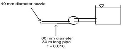
Solved The Pump Shown In The Figure Adds 25 Kw To The Water Chegg The power added by the pump is given as 25 kw and the **volumetric flow rate **of the water is given as 0.04 m^3 s. to determine the water depth, h, in the tank, we can use the equation for power: power = (density of water) * (acceleration due to gravity) * (volumetric flow rate) * (water depth). Solution for the pump shown in figure (2) adds 25 kw to the water and causes a flow rate of 0.04 m³ s. determine the flow rate expected if the pump is removed…. The pump shown in the figure adds 25 kw to the water and causes a flow rate of 0.04 m^3 s. determine the flow rate expected if the pump is removed from the system. assume f =0.016 for either case and neglect minor losses. the nozzle diameter is 40 mm, the pump diameter is 60mm, and the pump is 30 m long. The pump shown in the figure adds 25 kw to the water and causes a flow rate of 0.04 m^3 s. determine the flow rate expected if the pump is removed from the system. assume f =0.016 for either case and neglect minor losses.

Solved Question 3 The Pump Shown In Figure A Adds 25 Kw To Chegg The pump shown in the figure adds 25 kw to the water and causes a flow rate of 0.04 m^3 s. determine the flow rate expected if the pump is removed from the system. assume f =0.016 for either case and neglect minor losses. the nozzle diameter is 40 mm, the pump diameter is 60mm, and the pump is 30 m long. The pump shown in the figure adds 25 kw to the water and causes a flow rate of 0.04 m^3 s. determine the flow rate expected if the pump is removed from the system. assume f =0.016 for either case and neglect minor losses. Q4: the pump shown in figure (2) adds 25 kw to the water and causes a flow rate of 0.04 m³ s. determine the flow rate expected if the pump is removed from the system. assume f= 0.016 for both case and neglect minor. Produce the energy balance equation for the water flowing through the layout shown in figure b.2 with each of the terms described. calculate the height h (see figure b.2). determine the flow rate expected if the pump is removed from the system. The pump shown in fig. $p 8.94$ adds $25 \mathrm{kw}$ to the water and causes a flowrate of $0.04 \mathrm{m}^{3} \mathrm{s}$. determine the flowrate expected if the pump is removed from the system. assume $f=0.016$ for either case and neglect minor losses. Step by step engineering solutions, including the answer to "the pump shown in the given figure adds 25 ~kw to the water and causes a flow rate of 0.04 ~m^3 s. determine the flow rate expected if the pump is r ".

Solved Q2 The Pump Shown In Figure Below Adds 25 Kw To The Chegg Q4: the pump shown in figure (2) adds 25 kw to the water and causes a flow rate of 0.04 m³ s. determine the flow rate expected if the pump is removed from the system. assume f= 0.016 for both case and neglect minor. Produce the energy balance equation for the water flowing through the layout shown in figure b.2 with each of the terms described. calculate the height h (see figure b.2). determine the flow rate expected if the pump is removed from the system. The pump shown in fig. $p 8.94$ adds $25 \mathrm{kw}$ to the water and causes a flowrate of $0.04 \mathrm{m}^{3} \mathrm{s}$. determine the flowrate expected if the pump is removed from the system. assume $f=0.016$ for either case and neglect minor losses. Step by step engineering solutions, including the answer to "the pump shown in the given figure adds 25 ~kw to the water and causes a flow rate of 0.04 ~m^3 s. determine the flow rate expected if the pump is r ".

Solved Q 8 The Pump Shown In The Figure Adds 25 Kw To The Chegg The pump shown in fig. $p 8.94$ adds $25 \mathrm{kw}$ to the water and causes a flowrate of $0.04 \mathrm{m}^{3} \mathrm{s}$. determine the flowrate expected if the pump is removed from the system. assume $f=0.016$ for either case and neglect minor losses. Step by step engineering solutions, including the answer to "the pump shown in the given figure adds 25 ~kw to the water and causes a flow rate of 0.04 ~m^3 s. determine the flow rate expected if the pump is r ".

Solved The Pump Shown In The Figure Adds 25 Kw To Chegg

Comments are closed.